Appendix E
Calculation Methods AppendixPart II.C.3.b
II.C.3.b Fuel Combustion Emissions for Facilities with On-Site Generation
or Boiler Units
Some facilities use on-site fuel combustion to run power
generation, cogeneration, or boiler units, and then use the resulting
electricity, steam, heat, and hot water in various subprocesses. These
facilities may also source additional energy from off-site, particularly for
electricity. Within the facility, however, there is no difference between
consuming the portion of energy sourced from on-site units and consuming the
portion of energy purchased from a third party.532F
For this reason, the calculations assume that the proportional use of each
energy type is the same across all sourcese.g., that
electricity from an on-site unit and electricity sourced from the grid was used
in the same proportions as the facility-wide data in question 3.9 for each
subprocess. The questionnaire required facilities that reported the use of
on-site power generation, cogeneration, or multipurpose nonelectric boiler
units to first allocate fuel use among these units and all other on-site fuel
combustion in question 3.7. For these facilities, the subprocess-specific
quantities of fuel use reported in question 3.8 only represented fuel that was
not first combusted in the generation or boiler units, to avoid double
counting. The calculations instead used data in questions 3.9 through 3.12 on
subprocess-specific use of electricity, steam, heat, and hot water to allocate
the emissions from the power generation, cogeneration, and boilers to
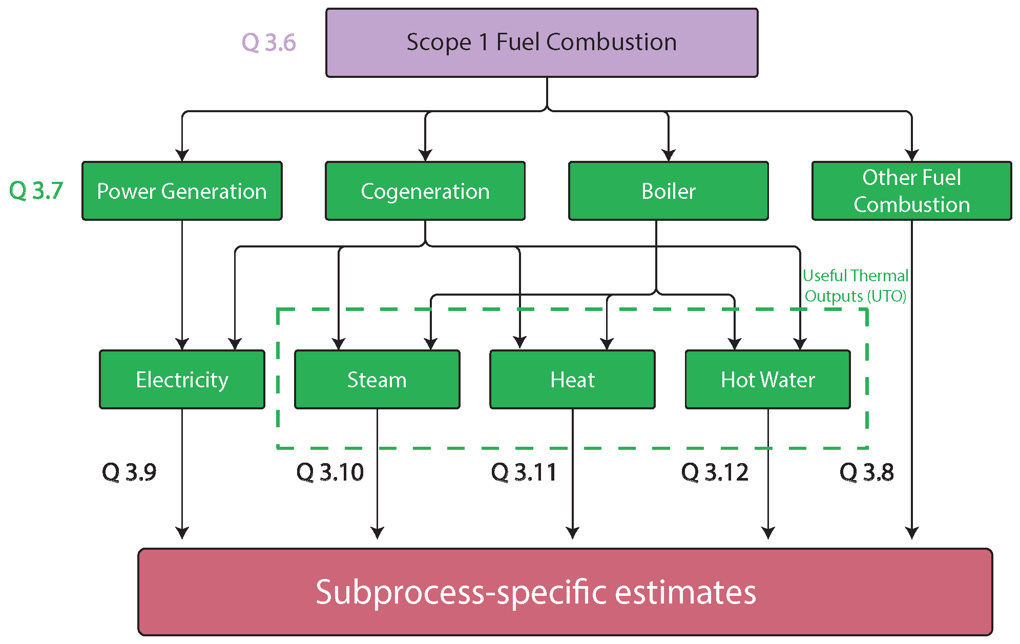
subprocesses. This mapping of fuel combustion in power generation,
cogeneration, boiler units, and all other fuel combustion to electricity,
steam, heat, hot water, and question 3.8 fuel use to develop
subprocess-specific emission estimates is shown in figure E.1, below.
Figure
E.1
Mapping of facility-wide scope 1 fuel combustion emissions to
subprocess-specific estimates
Source: Compiled by the USITC.
Note: The “Q” labels in the diagram
above indicates the question number in the Commission’s facility-level
questionnaire gathering this information. USITC, Greenhouse Gas (GHG)
Emissions Intensities Questionnaire: Facility-Level, 2024, section 3.
Calculating the subprocess-specific emissions for other fuel
combustion (from question 3.7) is similar to the subprocess-specific fuel
combustion calculation for facilities with less complicated energy sourcing.
The only difference is that the facility-wide emissions are multiplied by an
additional ratio to remove the fuel-specific emissions associated with
generation and boiler units (equation E.16). This ratio is the amount of fuel
used in all other on-site fuel combustion in question 3.7 ( ) divided by the total fuel use reported in
question 3.7 ( ).
|
|
|
|
As shown in figure E.1, fuel combustion quantities from
question 3.7 ( ,
,
) determine the share of the facility-wide,
fuel-specific emissions to apply to the facility’s power generation,
cogeneration, and boiler units, respectively. Cogeneration units produce a mix
of electricity and useful thermal outputs (steam, heat, and hot water), and
boilers may produce more than one type of useful thermal output. Equations E.17E.19 first
compute the fuel combustion emissions for each of these units ( ,
,
), before further allocating the unit
emissions to their different energy outputs.
|
|
|
|
|
|
|
|
|
|
|
|
The fuel-specific emissions for each unit are then totaled
across fuel types to estimate total fuel combustion emissions for each unit.
The formula for power generation units is shown as an example in equation E.20.
|
|
|
|
Before estimating subprocess-specific scope 1 emissions from
electricity use, the calculations split apart emissions from cogeneration units
between electricity and useful thermal outputs .
The DOE’s identification number for the facility’s cogeneration units, as reported
in question 3.3c, is used to identify the unit’s electric allocation factor ( ) in eGRID’s plant-level data.533F
Equation E.21 uses this factor to estimate the share of the cogeneration unit’s
emissions associated with the unit’s electric power output ( ).
|
|
|
|
For any facilities generating more electricity than they
used at the facility, the questionnaire allowed a negative value to be reported
in question 4.1 for electricity purchases. Equations E.22.a and E.22.b
calculate scope 1 fuel combustion emissions associated with electricity for
facilities with negative net purchases and positive net purchases,
respectively. Equation E.22.a incorporates the ratio of electricity used
on-site, where represents negative net purchases (electricity
sold off-site) and ( ) is the sum of on-site electricity generation
reported in question 3.3.
Else:
Then, equation E.23 allocates facility-wide scope 1
electricity generation emissions ) to subprocesses .
|
|
|
|
The next set of equations split emissions from non-electric
cogeneration ( and boiler units to develop emissions estimates for steam,
heat, and hot water use. Non-electric cogeneration emissions are the total
emissions associated with on-site generation of useful thermal outputs
(equations E.24 and E.25):
|
|
|
|
|
|
|
|
First, if a facility reported net sales of these outputs ( ,
equations E.26.a and E.27.a applied a ratio of thermal outputs used on-site ( ) to outputs generated on-site ( ).534F
This ratio removes the emissions associated with thermal outputs that were sold
from the facility and used instead by third parties. When a facility sells more
thermal output than it purchases, no scope 2 emissions are estimated for the
quantity of purchased output; the quantity purchased is instead treated as if it
were sourced from the facility’s on-site generation of that thermal output.
This is consistent with how electricity was treated (using data on net
electricity purchases) and with GHG Protocol guidance.535F
In addition to adjusting for any net sales of thermal outputs, equations E.26
and E.27 proportionally break out emissions for cogeneration and boiler units
based on the relative quantities of each type of thermal output produced from
each unit (e.g., ( ). Equations E.26 and E.27 are calculated for
each of the types of useful thermal output (steam, heat, and hot water).
Equation E.28 combines the emissions for each useful thermal output from
cogeneration units with the emissions for that output from boiler units.
|
|
|
|
|
|
|
|
|
|
|
|
|
|
|
|
|
|
|
|
|
|
|
|
|
|
|
|
|
|
|
|
Equation E.29 then allocates the estimates for scope 1 fuel
combustion associated with the facility’s generation of steam, heat, and hot
water at on-site units ( ) to each of the subprocesses. The allocations
for steam, heat, and hot water were reported directly in questions 3.103.12 as
estimated percentage shares ( ).536F
|
|
|
|
Finally, equation E.30 totals the subprocess-specific
estimates for scope 1 fuel combustion emissions ) from scope 1 electricity, steam, heat, hot
water, and other fuel combustion. For fuel combustion not used in power
generation, cogeneration, or boiler units, the subprocess-specific emissions
are first totaled across all fuel types ( ).
|
|
|
|
From this point in the calculations, the allocation of any
emissions from ambient heating and the aggregation of subprocesses to unit
process emissions for scope 1 fuel combustion follow the same steps as with
simpler facilities (equations E.11E.13).
These final steps yield scope 1 fuel combustion unit process emissions ( for the product-level emissions inventories.